- Phone: 800-492-1252
- Fax: 440-368-3569
- E-mail: info@spartanwatertreatment.com
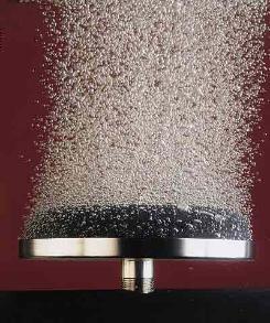
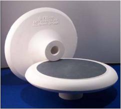
Ozone contactors with fine bubble diffusers dissolve ozone into water via a porous stone. The porous stone is ozone-resistant ceramic held in place by stainless steel. As the bubbles rise in the contact vessel, they transfer the ozone into the liquid phase. An advantage of the bubble diffuser contactors is that they can use the pressure of the ozone generator to drive the gas through the diffusers without any additional energy input. The offset is the cost to build the deep basin contactors. On this page are various images of fine bubble diffusers and contact chambers.
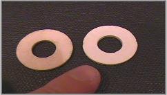
The components of ceramic bubble diffusers are usually held in place with stainless steel hardware and ozone resistant gaskets (Hypalon, Viton, or Teflon). Many ceramic designs have been offered for sale that eliminate the need for gaskets. The diffusers can be disks or tubes. Tubular diffusers which are used for air fed systems have higher gas flow rates which range from 2-6 CFM/diffuser. Disks or domes, which are more often used with oxygen feed, have flows of 0.5-2 CFM/diffuser.
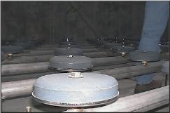
Fine bubble diffused aeration systems are located in an array in deep multi chamber basins. The spacing of the fine bubble diffusers is important and typically is less than or equal to 4 square feet per diffuser. The arrays are designed to maximize ozone transfer efficiency. The connecting pipe can be stainless steel or PVC. The submerged level of the diffuser impacts ozone transfer efficiency. At sea level, the diffusers are typically submerged 16 to 20 feet deep. Different ceramic materials produce different pressure drops as a function of the gas flow. Transfer efficiency for air fed ozone generators and bubble contact diffusers is approximately 85% while for oxygen fed ozone generators feeding high concentration ozone to bubble diffusers the transfer efficiency can be 95%.
The chambers create a serpentine path for the water to travel with the objective of creating plug flow through the contactor and maximizing the hydraulic detention time (minimizing short circuiting of the flow through the contactor). Not all chambers of the contactor will necessarily have diffuser arrays on the bottom. In drinking water treatment, where chemical oxidation is the objective 2-4 chambers are used. In drinking water treatment for disinfection, 6-8 chambers are used. If inactivation of Cryptosporidium is needed 10 or more chambers might be employed.
Bubble diffusers are normally positioned in the first 1-3 chambers of the contactor. The flow through the chambers with the diffusers can be alternating counter current/co-current flow or all counter current. Counter current flow enhances transfer efficiency. Since the first chamber will be exposed to water with the highest ozone demand, more diffusers should be employed here.
A discussion of bubble diffuser contactors can also be found elsewhere in the website in a presentation on surface water treatment rules and in a presentation discussing drinking water plant operations . These papers contain illustrations and calculations regarding the effectiveness of various designs.
The apparent hydraulic detention time (HDT – the simple geometric volume of the contact vessel divided by the flow rate through the vessel) is most often not the effective hydraulic detention time due to short circuiting of the flow through the vessel. Designers will often use another measure of detention time referred to as T10. This value represents the time for 90% of the water to pass through the contact vessel. Typically, the value is around 65% of the apparent HDT. T10 is determined based on results with past designs, sophisticated flow modeling programs or tracer studies.
Understanding the effective HDT is critical for applications such as disinfection. To insure the inactivation of micro organisms, certain concentration X time (CT) values must be achieved. The effective HDT or T10 is used for these calculations.
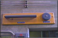
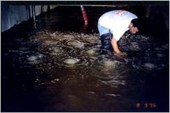
The contactor is normally fitted with pressure/vacuum relief valves to prevent structural damage to the vessel which are made of reinforced concrete. Contactors are also fitted with ceiling and side wall manholes for inspecting the diffusers and insuring that the bubble pattern is acceptable and for periodic replacement of gaskets. Other essential components of the system are sample ports for measuring ozone residuals in the various chambers, gas flow rate.


Spartan Environmental Technologies, LLC
PO Box 1270
Mentor, OH 44061-1270